
 EN
EN RU
RU
A turbocharger fits on a workbench, yet producing it is a systems problem measured in airflow, heat, microns and rotating mass. A new full-cycle facility in Protvino brings more of that problem under one roof. Its value will depend not simply on installed machines, but on whether design, machining, welding, balancing, assembly, testing and field feedback operate as one controlled rotor system.
The announcement described a deeper manufacturing boundary
On 27 August 2026, Expert reported that TurboKomplekt had opened a new production building in Protvino, Moscow Region. The reported products are turbochargers for diesel trucks, light commercial vehicles and agricultural machinery. The project was reported at 1.8 billion roubles, including a 1.2 billion-rouble concessional loan from the Industrial Development Fund.
Installed equipment includes turning and milling centres, electron-beam welding equipment, balancing machines and semi-automatic assembly equipment. The company describes a full cycle from gas-dynamic design to finished-product testing. Housing machining, working wheels and bearings, rotor welding and balancing are among the localised operations. The intended result is not merely a larger assembly shop: it is control over interfaces that determine whether a fast rotating product survives its duty cycle.
These are statements in a launch report, not an independent audit of output, yield, localisation or field reliability. A useful operational reading therefore asks what evidence the new boundary must generate, which assumptions remain undisclosed and how the plant can demonstrate stable capability after the ceremonial opening.
The capacity figures require a transparent note
The source says full-capacity output is planned to rise from 46,000 to 90,000 turbochargers a year and characterises the increase as 45%. Those endpoints do not produce a 45% increase under the usual calculation. The difference is 44,000 units, or about 95.7% of the 46,000-unit starting point. There may be an undisclosed distinction between design capacity, actual output, product mix or the comparison period.
Without such an explanation, the endpoints and percentage should be presented separately rather than forced into agreement. This matters because capacity claims guide staffing, supplier commitments, finance and customer expectations. Installed nameplate capacity is not sellable output. Effective capacity is reduced by product mix, setups, maintenance, qualification batches, inspection, rework and bottlenecks.
A credible ramp plan distinguishes four numbers
- Installed capacity: the theoretical equipment rate under stated assumptions.
- Demonstrated capacity: sustained conforming output during an observed run.
- Planned output: volume matched to demand, labour, material and working capital.
- Shipped output: accepted product released after every quality gate.
Reporting all four prevents a launch from being mistaken for a stable operating system. It also exposes the true constraint as the ramp proceeds. A plant can double one machine group's capacity while final output remains constrained by rotor balancing, test benches, approved castings, skilled operators or one qualified bearing component.
Gas-dynamic design begins the physical route
A turbocharger couples two gas machines through one shaft. Exhaust energy drives the turbine; the compressor raises intake-air pressure. Wheel geometry, housing passages, clearances and control behaviour must match an engine's flow, pressure ratio, temperature and transient demands. That matching is a family decision rather than a single peak-efficiency target.
A unit that performs well at one point can respond poorly at low speed, overspeed at another condition or push the compressor toward unstable operation. Design intent therefore needs traceable assumptions, simulation versions, material limits and validation cases. The production route should know which characteristics protect each intended operating condition.
A released definition includes more than drawings. It connects aerodynamic surfaces, tolerances, critical characteristics, material specifications, heat treatment, joint design, balance limits, assembly conditions and the test plan. When any of these changes, the organisation must know which part numbers, tools, programmes, inventory and evidence are affected.
Design ownership is valuable because field evidence can return directly to engineering. It becomes dangerous if rapid local decisions bypass configuration control. A formal change board should separate correction, cost reduction, supplier substitution and performance development, then assign the appropriate analysis and requalification.
Castings and blanks carry hidden history
The visible machining operation cannot repair every weakness inherited from a casting or metal blank. Chemistry, inclusions, porosity, grain condition, heat treatment and dimensional allowance influence machinability and service strength. Incoming identity and process records must follow each critical batch into production and, where required, into the finished unit's genealogy.
Housing castings operate in different environments. The turbine side experiences hot exhaust and thermal cycling; the compressor side controls clean-air geometry and interfaces. A common purchasing label is not enough to define either duty. Supplier approval should combine document review with material verification, dimensional sampling and process trials.
A first acceptable lot does not establish indefinite capability. Trend data by supplier, mould, heat and defect mechanism reveal drift before it becomes a customer event. The source expects the share of imported materials to fall from 90% to 40%. That is an imported-material share, not a complete localisation percentage.
The indicator says nothing by itself about the origin of equipment, software, intellectual property, spares, services or value added. It needs a documented numerator, denominator and period. A change of accounting definition could otherwise look like technical progress even when the physical supply risk remained unchanged.
Machining creates the reference system
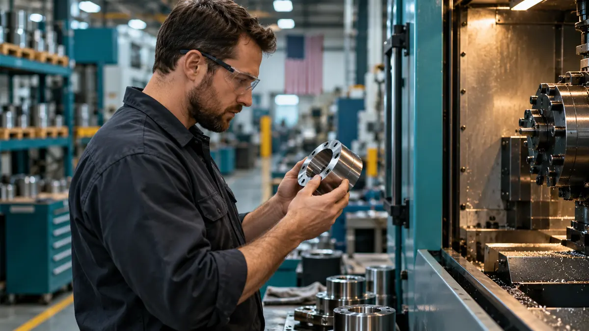
Turning and milling centres create bores, faces, seats and passages that locate the rotating group and connect it to engine air, exhaust, oil and control interfaces. Their dimensions are relational. A correct bore diameter can still fail if its axis is misaligned with another reference or if a sealing face is distorted.
Critical characteristics may include concentricity, runout, flatness, surface condition, fits and passage integrity. The exact specification belongs to the approved product definition; operators should not infer it from generic practice. Measurement methods must be capable at the required tolerance and protected from temperature, fixture and operator effects.
Process control starts before final inspection. Tool condition, offset, fixture cleanliness, clamping, programme revision and coolant state can shift output. First-off approval after a setup and periodic checks during the run should be linked to machine, tool, operator and material batch. Suspect parts must be contained back to the last known good result.
A machining control plan can ask
- Which feature is critical to safety, balance, sealing, lubrication or mounting?
- Which process input can move that feature, and how quickly can it drift?
- What check detects the change before more parts are exposed?
- How are suspect parts identified, segregated and dispositioned?
- Who may adjust an offset or programme, and where is the reason recorded?
Statistical signals are useful only when the measurement system is trusted. Gauge repeatability, calibration and correlation between shop-floor and laboratory methods should be established before capability indices are used as proof. Otherwise a stable chart may describe the gauge rather than the product.
The rotor concentrates several risks
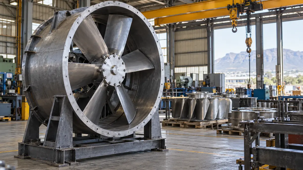
The shaft, turbine wheel and compressor wheel form a rotating system whose small mass errors become significant at speed. Geometry, material, joining, assembly position and balance cannot be managed as unrelated inspections. Each upstream result changes the condition seen by the next operation.
Electron-beam welding appears in the reported equipment set. The process can create a concentrated joint in a controlled chamber, but the source does not disclose its qualified parameters or product coverage. Each joint still requires an approved procedure, equipment readiness, cleanliness, part fit, traceable settings and defined acceptance evidence.
Welding changes more than joint strength. It can affect alignment, distortion, local material condition and distribution of mass. Post-weld checks therefore need to connect joint integrity with dimensional and balance requirements. A visually acceptable joint cannot substitute for evidence relevant to the product's load and speed.
Bearings and oil paths are equally central. A component can meet its drawing while contamination, wrong orientation, blocked flow or unsuitable clearance damages the assembled unit. Clean handling, verified passage condition and controlled lubrication during assembly are production requirements, not housekeeping details.

Balancing is a sequence, not a final rescue
A balancing machine does not turn inconsistent components into a robust design. Balance should be built through component control, shaft-and-wheel joining, intermediate checks and final rotating-assembly verification appropriate to the approved route.
Low-speed balancing can identify mass distribution under one condition; higher-speed verification can reveal behaviour closer to operation. The applicable stages, limits and corrections depend on the product. The launch report confirms balancing equipment, not a particular validation sequence, limit or claimed performance.
Correction has its own controls. Material removal or another approved method must stay within defined zones and limits. Repeated correction can signal upstream variation in wheels, welds or assembly. Recording initial condition, correction and final result creates diagnostic data rather than a simple pass mark.
Fixtures and adapters participate in the measurement. Their wear, cleanliness and own balance can create false signals. Reference artefacts and scheduled correlation help distinguish product movement from equipment movement. Environmental and setup conditions also belong in the record when they can affect the result.
Assembly protects accumulated precision
Semi-automatic equipment can improve consistency, but automation does not make a process self-validating. Correct parts, revision, orientation, cleanliness, force, torque, sequence and operator response to an exception remain controlled inputs. Interlocks should prevent known mistakes while preserving evidence when a stop occurs.
Component genealogy matters when similar variants share a line. Scanning or another mistake-proof method should connect housings, rotating group, actuator and test record to one serial identity. A physical fit is not proof that a component belongs to the ordered configuration.
Clean zones should follow risk, not appearance. Exposed bearings, oil passages and sealing interfaces need protection from chips, abrasive residue, fibres and mixed consumables. Tools used near critical internals require their own condition and foreign-object controls.
Standard work should define both the normal route and abnormal response. If force, torque or fit is outside its window, the unit is contained; the operator should not quietly repeat the step until it passes. Repetition without diagnosis erases evidence and moves uncertainty toward the customer.
End-of-line testing closes only one loop
The source says the cycle ends with finished-product testing but does not publish the specification. A defensible architecture could cover leakage, actuation, rotational behaviour, vibration and relevant flow response, according to the validated product and customer requirement. These are analytical control possibilities, not disclosed contractual tests.
An end test proves only the conditions it applies. It cannot fully reproduce material fatigue, thermal cycles, contaminated oil, installation errors or years of variable duty. Design validation, process validation, audit tests and field monitoring therefore complement the production gate.
Every stand needs controlled software, fixtures, sensors, calibration and reference checks. Limits must be tied to product revision. A result without serial identity, time, stand and configuration is difficult to investigate later. Interrupted and borderline tests need defined responses rather than discretionary retesting.
False rejects waste capacity, while false accepts export risk to the customer. Test-system analysis should quantify repeatability and challenge known conditions. The stand itself is part of the manufacturing process and should enter maintenance, change control and capability reviews.
Quality should travel upstream
When a unit fails balance or end test, the fastest action is containment. The most valuable action is attribution: tracing the symptom to design, material, machine, tool, weld, component, assembly or test system. That turns a failure from an isolated expense into information for prevention.
A nonconformance record should preserve original evidence before repair. Rework needs an approved route and renewed checks; it should not silently convert a failed unit into an ordinary pass. Scrap and rework trends belong in capacity and cost calculations because they consume the same constrained resources as good output.
Field returns need the same discipline. Product identity, engine application, installation, operating history and failure evidence should feed a structured review. Suppliers and customers can then work from a shared defect definition rather than competing narratives.
The strongest metric is not simply low reported defects. It is the speed and reliability with which a signal is contained, explained, corrected and verified without recurrence. A temporarily low return count can hide weak detection or delayed service feedback.
Localisation must preserve change discipline
Replacing an imported material or component can improve continuity and shorten logistics, but a local source is still a technical change. Equivalence requires evidence against the product function, process and duty, not only a matching certificate, price or nominal grade.
A qualification ladder can proceed from documentation and samples through laboratory checks, machining trials, assembly, bench validation, pilot lots and monitored field use. Its depth should follow risk. Parallel sourcing may be maintained until repeatability and capacity are demonstrated.
Supplier development is part of the factory system. Forecast visibility, defect feedback, agreed measurement methods and change notification help a supplier improve. Punitive inspection at receipt cannot compensate indefinitely for an unstable upstream process.
Dependency maps should include special tooling, welding consumables, gauges, sensors, controls, software, spares and service competence. A localised headline product can still stop because one small qualified dependency is unavailable, obsolete or supported by only one specialist.
Customers connect two industrial systems
The report says customers include manufacturers in Russia and the Minsk Motor Plant in Belarus. That makes configuration and feedback across organisational boundaries especially important.
Customer approval may differ by engine family and application. A unit for a truck, light commercial vehicle or agricultural machine can face different installation, transient, contamination and service conditions. One successful product does not qualify every derivative or future material change.
Interface control should define drawings, change notices, order configuration, packaging, trace records, acceptance evidence and failure-return procedures. Export continuity also depends on predictable documents and service support, not just physical output.
A practical ramp scorecard
- First-pass yield and demonstrated rate at machining, welding, balance, assembly and test.
- Critical-feature capability supported by measurement-system studies.
- Supplier acceptance, imported-material share under a stable definition and qualified alternatives.
- Rework, scrap and containment hours by attributable cause.
- Test escapes, field returns and recurrence after corrective action.
- Product-mix attainment, changeover loss, maintenance loss and customer delivery performance.
The full cycle was measured in microns
Protvino's new building brings valuable technical stages together. Its 1.8 billion-rouble scale, concessional funding and planned output show industrial ambition. Yet the durable asset is not floor area or any single machine. It is the ability to preserve design intent through thousands of small transformations.
The rotor makes that principle visible. A material batch, machined axis, welded joint, bearing surface, balance correction and clean assembly all meet in one fast rotating system. Final testing can screen the result, but it cannot manufacture discipline after the fact.
A credible full cycle therefore produces two outputs: turbochargers and evidence. The first serves engines; the second proves configuration, process stability, traceability and learning. If both rise together during the ramp, localisation becomes a resilient capability rather than a substitution count.




















HOT NEWS INTERNATIONAL
Leave a comment